Sunday, January 11, 2009
We've built motors in 10 minutes, but this one really does go together in 30 seconds or less. You can time yourself once you have all the pieces in front of you. Start the timer. Set the screw in the center of the disk magnet. Cut the alligator test lead in half, and strip the insulation from the last inch of the cut end, so the strands of wire spread out like a brush. Hold the alligator clip against the flat end of the battery. Bring the button end of the battery to touch the point of the screw, and lift the screw and magnet an inch off the table (the screw will stick to the battery because of the magnet). Gently hold the brush end of the wire against the edge of the magnet. Stop the timer, since the screw and magnet are spinning around like crazy.
Click on image for a larger pictureWhat you need
Click on image for a larger picture


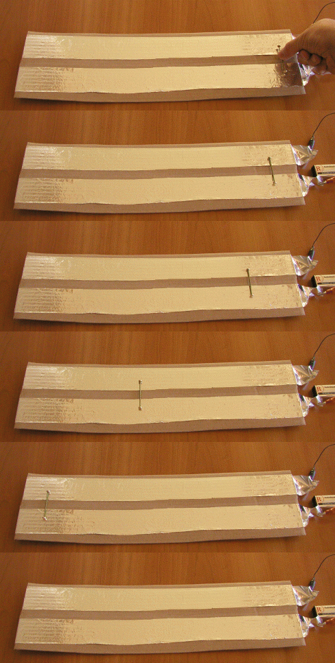
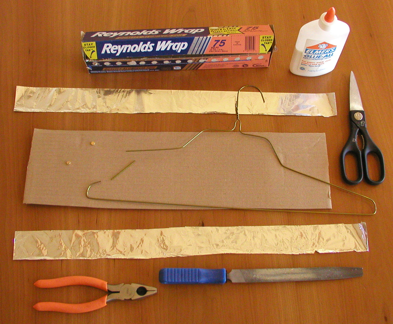
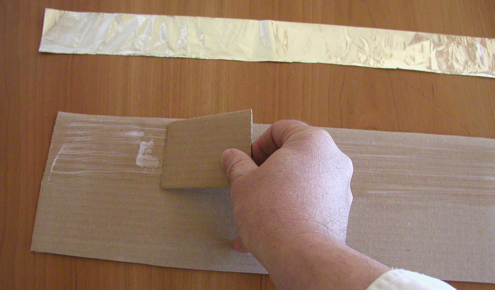
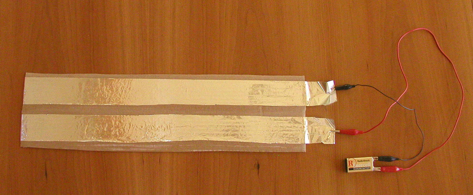
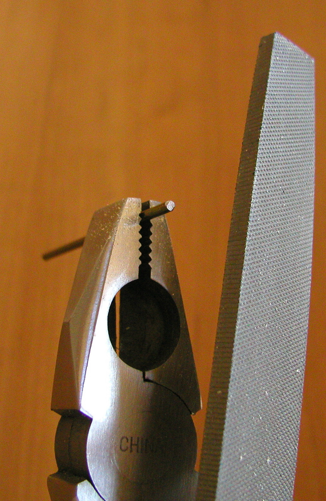
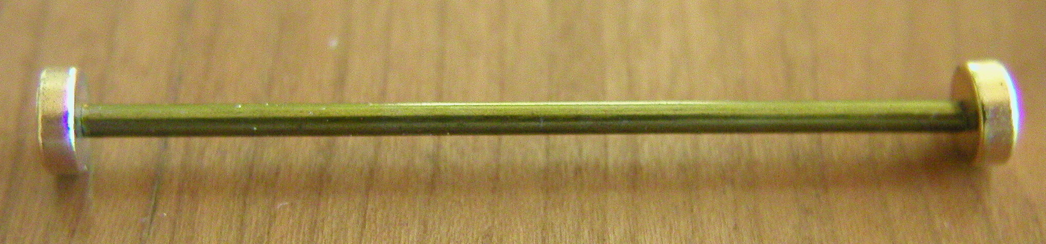
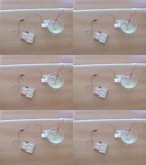
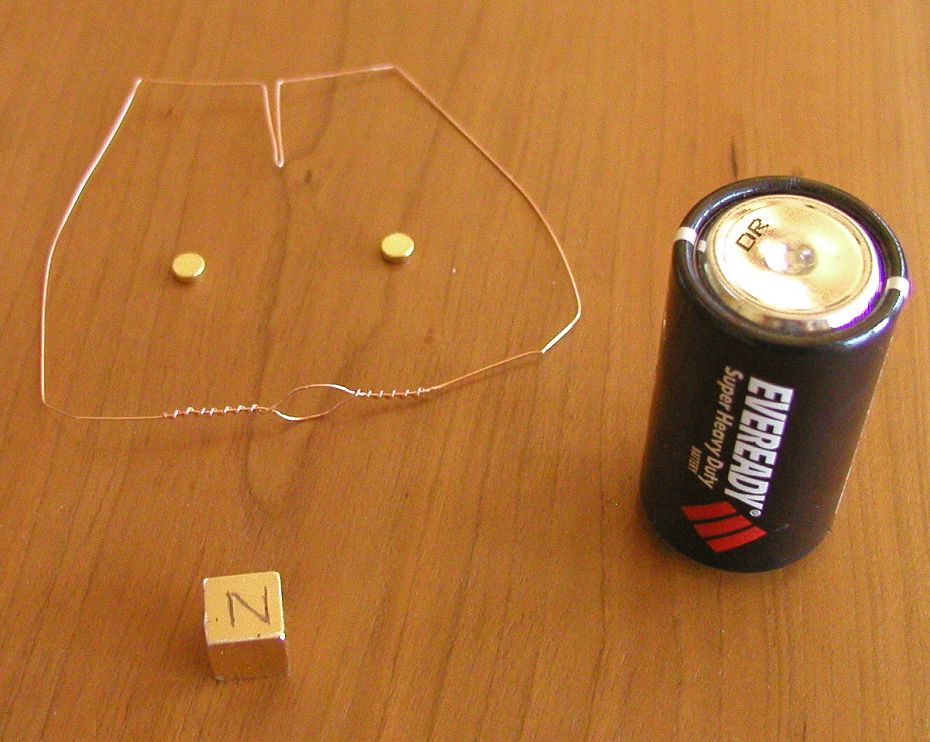
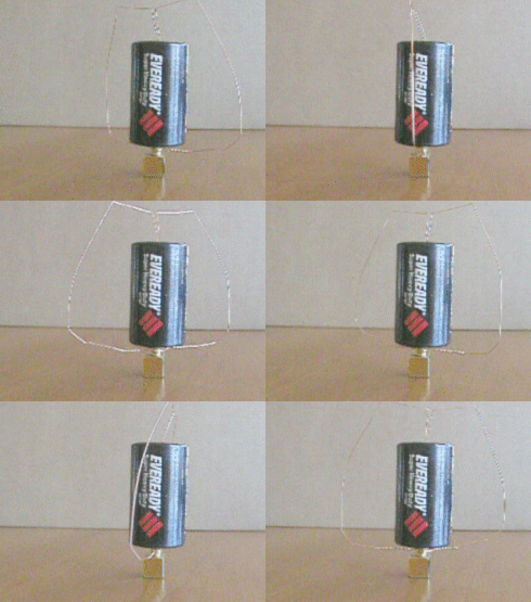
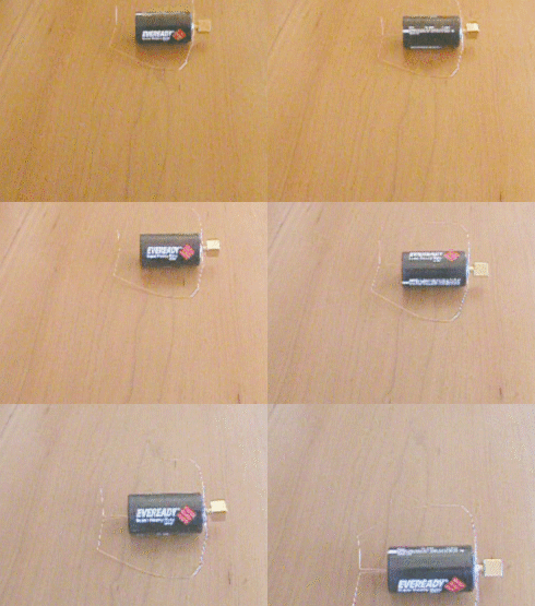
A railgun is a device for accelerating an object by running electric current through it along a pair of rails. When large amounts of power are used, the railgun becomes a potent weapon. But the principles can be demonstrated safely by using a smaller amount of power, in our case, from a 9 volt battery. When a small amount of power is used, the rails can be re-used many times. If larger amounts of power are used, the railgun becomes a one-shot device, as the rails are destroyed in the process of shooting the gun, due to arcing and flexing of the rails. There are several types of rail gun, each with a different method of accelerating the object. This version is called a linear homopolar motor. We start by spreading a thin layer of glue on the base, to hold down the foil strips. The foil strips are then placed on the base, about a half inch apart, and smoothed down with fingers to remove wrinkles. The extra 2 inches is left hanging over one side, to make it easy to clip on the leads for the battery. Next we attach the battery with the clip leads. We won't worry about battery polarity at this time -- if the gun shoots the wrong way, we will reverse the battery. The nest step is to file the ends of the coathanger wire flat. This will allow the magnets to stick flat to the ends of the wire axle. If the filing is done carefully to make the flat ends perpendicular to the wire, then there will be less wobbling as the magnets travel down the rails. Now the magnets are placed on either end of the wire axle. The magnets should have their poles facing in opposite directions. The magnets repel one another when aligned this way, but will still stick firmly to the steel axle. No glue is necessary, as the magnets are very strong. To fire the railgun, just drop the wheels on the rails. They will start to accelerate immediately. If they don't move at all, the magnets are probably not pointing the same way. Lift the wheels, and flip one magnet, and try again. If it still doesn't work, check the battery and the connections. If the wheels move in the wrong direction, you can either start them at the other end, or reverse the battery. Click on the photo below to see the railgun in action. The homopolar motor was one of the first motors ever built. Michael Faraday built one. There are many different designs. The one shown below is only one of them. Click on the picture to see it run. A magnet is placed north pole facing up in a bowl of vinegar. The magnet is one of our super-powerful ones from our catalog. Suspended over it is a heavy piece of copper tube or wire, hanging from a flexible stranded wire alligator clip. The vinegar covers the tube to a depth of about a half of an inch. The tube does not quite touch the magnet, but is free to swing around. A piece of aluminum foil also rests in the vinegar (this can be a copper wire instead, it is not critical). When we connect a source of about 30 to 50 volts (some 9 volt batteries connected in series) to the foil and the tube, the tube starts to revolve around the magnet. We also get lots of bubbles of hydrogen and oxygen, but for this project that is just a side effect. We have created a homopolar motor. Unlike our previous motors, this one does not change the poles of an electromagnet from north to south and back. As the current flows through the copper wire (or tube in our case), a magnetic field is created around it. This magnetic field interacts with the magnetic field of the magnet at the bottom of the bowl. The arrangement is set up so that the magnetic field in the wire exerts its force at a right angle to the magnetic field of the bottom magnet. This makes the wire circle that magnet. Another simple homopolar motor is shown below. The photo above shows the parts before assembly. There are three magnets -- two small disks, and one cube whose north pole we have marked with an "N". The magnets are from our catalog. There is a D cell battery, and a bare copper wire we have formed into a shape whose form will make sense shortly. The two small disk magnets are set on top of the North pole of the cube magnet. The loop in the bottom of the wire form is then placed in top of the two disks. The loop is just barely larger than the disks. The positive pole of the battery is then carefully placed on top of the disks, and the pointed end of the wire form is placed in the dimple at the top of the battery. When the whole structure is balanced on the cube magnet, the wire begins spinning around the battery. What is going on here is similar to what is going on in our vinegar version. The current from the battery is flowing through the wire on both sides of the wire form. This creates a magnetic field around the wire. This field interacts with the field from the cube magnet and the disks. The wire's field creates a force at right angles to the field from the magnets. This causes the right side of the wire to be pushed towards you, and the left side to be pushed away from you. This action continues until the battery runs down. Suppose we held onto the wire, and let the magnet move? We can do that by simply setting the battery on the table, on its side. Click on the photo to see an animation of what happens. The wire rotates until it hits the table. The force continues after the wire can no longer rotate, and so instead of the wire rotating, the battery and the magnets rotate. This makes the battery roll along the table like a steam roller. You can now see that we are very close to our railgun design. The railgun is really just two of these battery rollers connected end-to-end. The battery is now external, and the wires have been replaced by the rails. The magnetic field in the rails creates a force at right angles to the magnetic field of the railgun trolley's wheels, and causes them to roll.
Click on image for an animated pictureWhat you need
Click on image for a larger picture
Click on image for a larger picture
Click on image for a larger picture
Click on image for a larger picture
Click on image for a larger pictureFiring the railgun
Click on image for an animated pictureHow does it do that?
Click on image for an animated picture
Click on image for a larger picture
Click on image for an animated picture
Click on image for an animated picture
This toy is so simple to build, it goes together in 5 minutes from a few things found around the house. The toy is a high voltage motor that acts like a bell, with a clapper that bangs furiously from one can to the other and back again, sometimes several times per second. Occasionaly, the big blue spark snaps between the cans, to add interest to frenetic activity. To build the toy, you need: The photo may be all you need to get the toy working. Remove the pull-tops from both cans, and discard one of the pull-tops. Tie the thread to the other pull-top. Tape the other end of the thread to the center of the plastic rod. Place the two cans side-by-side two or three inches apart. Place the plastic rod on top of the two cans, so the pull-tab dangles freely about an inch from the table. Tape the bare end of one wire to the left can. This is the ground wire, and the free end should be connected to an electrical ground, such as a cold water pipe, or the metal frame of a computer. If a good electrical ground is not convenient, you can just hold onto the free end, since your body is a good enough ground for this device. Tape the other wire to the can on the right. It's free end will be connected to a source of high voltage. This is easier than it sounds, since a safe source of high voltage is right in front of you when you watch television or use a computer with a CRT monitor. In the photo above, you can see that the toy is sitting on top of a television. About two square feet of aluminum foil is pressed onto the face of the TV screen. It sticks there because the TV screen is highly charged with electricity. The free end of the right can's wire is attached to the aluminum foil. You start the toy by turning on the TV. The pull-top gets pulled to one can, but when it hits it, it gets pulled to the other can, and then repeats. Inside a television, a high voltage is used to send electrons to the screen at high speed, to create the picture. By placing a large conductor on the front of the screen, we can make a capacitor, to tap into some of that high voltage and put it to use outside of the television. The voltage is high, but the current is very small, so that touching the foil or the toy is no more harmful than touching a doorknob after scuffing your feet on the carpet. The can on the right is connected to the high voltage. The can on the left is connected to the ground, which can absorb all of the voltage we can send it, and still be ready for more. The pull-tab and the can on the left starts out without any electrical charge. We say they are at "ground potential". The can on the right is charged with a lot of free electrons, from the foil on the TV screen. These electrons repel the electrons in the pull-tab, and attract the positive nuclei in the pull-tab. The electrons in the pull-tab move to the side farthest from the high voltage can on the right. This leaves the right side of the pull-tab more positive than the left side. The positive side of the pull-tab is attracted to the highly negative can on the right, and the pull-tab jumps over to touch the can on the right. Once it touches the can, the electrons from the can rush onto the pull-tab, until it has the same high voltage charge as the can it is touching. The pull-tab and the can now have the same charge, and like charges repel. The charged pull-tab is now repelled by the can on the right, and moves to the left. The electrons in the can on the left are repelled by the pull-tab, and they move to the left side of the can, leaving the right side somewhat positive. This positive side attracts the negatively charged pull-tab, and draws it up to touch the can. Now the excess electrons on the pull-tab move onto the left can, and into the ground. The pull-tab is now at ground potential again. It swings back towards the can on the right, and the whole process starts over again. The device we have just built is called "Franklin's Bells", after a description of the device given by Benjamin Franklin, who used it to detect the approach lightning storms. He connected one end to his lightning rod on top of the house, and the other end to an iron water pump well connected to the ground. Of course Ben didn't use soda cans. He used bells. I built a pretty version with bells and set it up on top of the TV just like our first version. I left the clappers on the bells, even though they no longer serve any purpose. The bells are connected to the aluminum foil and the ground by thin copper wires you can just barely see in the photo. The bells are from a craft store. The clapper is one of the small round bells called "jingle bells".
Click on the photo to see an animated pictureHow does it do that?
A fancier version

Click on the photo to see an animated picture


Back in the 1960's my father taught me how to make the little electric motor we will make here. Sometime in the 1980's I saw a description of it in the magazine "Physics Teacher". Lately I have seen it described as Beakman's motor, after the science oriented TV show on which it recently appeared. The motor is simply a battery, a magnet, and a small coil of wire you make yourself. There is a secret to making it (which I will of course share with you) which is at the same time clever and delightfully simple. What you will need: We start by winding the armature, the part of the motor that moves. To make the armature nice and round, we wind it on a cylindrical coil form, such as a ball point pen or a small AAA battery. The diameter is not critical, but should be related to the wire size. Thin wire requires a small form, thick wire requires a larger form. Leaving a couple of inches of wire free at one end, wind 25 or 30 turns arounf the coil form. Don't try to be neat, a little randomness will help the bundle keep its shape better. The coil will end up looking like the photo below: Now carefully pull the coil off of the form, holding the wire so it doesn't spring out of shape. To make the coil hold its shape permanently, we will wrap each free end of the wire around the coil a couple of times, making sure that the new binding turns are exactly opposite each other, so the coil can turn easily on the axis formed by the two free ends of wire, like a wheel. It is not necessary, but I usually wrap a couple turns around these binding turns as well, threading the wire into the space between the large coil and the small coils that hold it together. This makes for a neat, tight package, as in the photo below: If this method of holding the coil together is too difficult, feel free to use scotch tape or electrical tape to do the job. The important thing is to keep the coil together, and to have the two ends of the wire anchored well, and aligned in a straight line, so they form a good axle. Now is where the secret trick comes in, the thing that makes the motor work. It is a secret trick because it is a small and subtle thing, and is very hard to see when the motor is running. Even people who know a lot about motors may be puzzled until they examine it closely and find the secret. Hold the coil at the edge of a table, so the coil is staight up and down (not flat on the table), and one of the free wire ends is lying flat on the table. With a sharp knife, remove the top half of the insulation from the free wire end. Be careful to leave the bottom half of the wire with the enamel insulation intact. The top half of the wire will be shiny bare copper, and the bottom half will be the color of the insulation. A quick sketch may help: Do the same thing to the other free wire end, making sure that the shiny bare copper side is facing up on both wire ends. The idea behind the trick is that the armature is going to rest on two supports made of bare wire. These supports will be attached to each end of the battery, so electricity can flow from one support into the armature and back through the other support to the battery. But this will only happen when the bare half of the wire is facing down, touching the supports. When the bare copper half is facing up, the insulated half is touching the supports, and no current can flow. The next step is to make the axle supports. These are simple loops of wire that hold up the armature and allow it to spin. They are made of bare wire, since they will also act to get electricity to the armature. Take a stiff piece of bare wire (copper or brass will work, as will a straightened paper clip) and bend it around a small nail to make a loop in the middle, as shown in the photo below. Do the same to another wire, so you have two supports. The base for this first motor will be the battery holder. It makes a nice base because it is heavy when the battery is installed (so the motor won't wobble) and because it has convenient holes in the plastic where we can attach the bare wire armature supports. Attach the support wires securely to the battery holder by winding the free ends several times through the small holes in the plastic at each end. Bend the support wires so the rings are just far enough apart for the armature to spin freely. Bend them apart a little and insert the armature into both rings, then bend them back so they are close to the coil, but not touching it. Insert the battery into the holder. Place the magnet on top of the battery holder just underneath the coil. Make sure the coil can still spin freely, and that it just misses the magnet. The finished motor looks like this: Note that there is a strip of paper stuck in between the battery and the electrical contact in the holder. This is the on/off switch. Remove the paper to allow electricity to flow into the motor, and replace the paper when you want to stop the motor and save the battery. Spin the armature gently to get the motor started. If it doesn't start, try spinning it in the other direction. The motor will only spin in one direction. If the motor still doesn't start, carefully check all the electrical connections. Is the battery connected so one support touches the positive end of the battery, and the other touches the negative end? Is the bare copper half of the armature wire touching the bare support wires at the bottom, and only at the bottom? Is the armature freely spinning? If all these things are correct, your little motor should be spinning around at a pretty fast rate. Try holding it upside down. The motor should spin in the opposite direction if the magnet is on top instead of on the bottom. Try turning the magnet upside down and see which direction the motor spins. If you want a motor that has the magnet on the side instead of the top or bottom, you can simply make a new armature, but this time lay the coil flat on the table when you scrape the insulation off of the top half of the free wire ends.A motor in 10 minutes
A quicky motor


