Sunday, January 11, 2009
This very simple toy keeps amazing me with new tricks. My friend Jef Raskin first described it to me, and we have both been having fun with variations ever since.
All it consists of is ten little magnetic beads on a carbon graphite composite rod.
The beads all repel one another, and arrange themselves in a way that clearly shows the effect of gravity -- the beads at the bottom are closer together than the ones at the top, forming a beautiful mathematical progression.
Click on image for larger picture
The fun doesn't stop there, though. Turn the rod upside-down, and the beads flow down like sand, arranging themselves once again in the same pattern, always staying separate.
Push down on the top bead, and then let it go. The ring shoots up into the air, and sticks to whatever ferromagnetic surface it hits, such as a filing cabinet or refrigerator. The effect is non-linear. Adding one more bead makes the top bead go farther than adding the previous bead did.
There are two configurations we like to play with. In one, we glue a bead to each end of the rod, with eight (or more) beads in the middle. This form allows us to stick it to the refrigerator, and peel it off like a zipper.
If you let it stick to the refrigerator, then pull the top or the bottom, the magnets bunch up at the other end. Then peel it off, and they jump back one by one into the original sequence.
It's mesmerizing just to turn it upside down again and again, and watch the beads orient themselves, flowing like water down the rod.
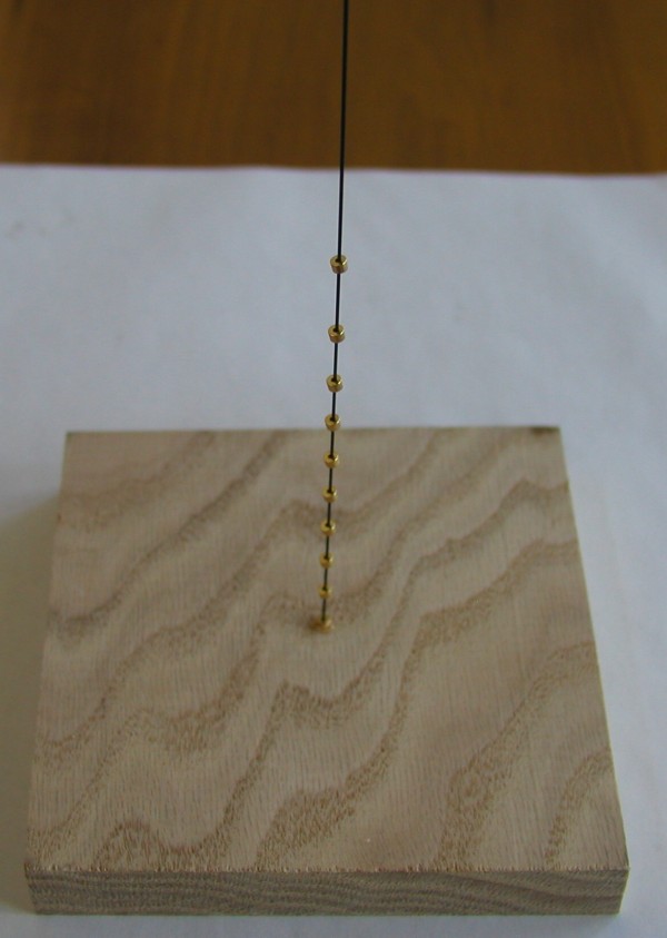
The second form is the Ring Launcher. In this form, the rod is glued into a hole in a block of wood, so it stays upright (or at a 45 degree angle if you want maximum horizontal range).
You can launch the rings at steel targets, or have competitions or battles between two launchers. Or, you can glue a bead to the top, and just play with it on your desk, shooting the beads up to the top, where they are silently repelled back down by the top bead.
Building the Ring Launcher
You probably don't need any further explanation, but for completeness, we show the construction steps below.
Click on image for larger picture
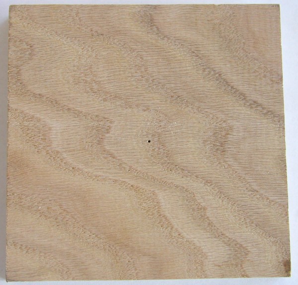
We start with a wooden block, and drill a small hole in the center.
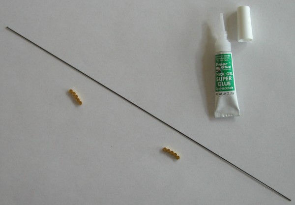
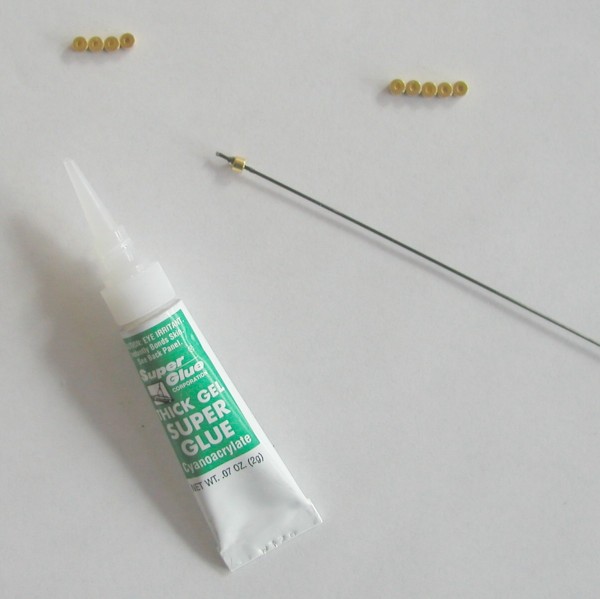
We carry the rods and the beads in our catalog. The rods are 10 inches long, and 0.03 inches in diameter. They are made from the same high strength graphite composite that high-end tennis racquets, fishing poles, and bicycles are made of. They will bend easily, and spring back to their original straight form. If bent too far, they will snap cleanly in two pieces.
The beads have holes in them that just fit over the rod. They are the same super high strength magnets as the others we carry in our catalog. Like those, they are gold plated to keep out moisture, and survive corrosion and abrasion.
Click on image for larger picture
Glue the rod into the hole, keeping the rod upright. We like to use Super Glue, as other glues take longer to harden, and don't hold onto the slippery rod as well.
Place one bead at the bottom of the rod, and let the glue stick it there.
Now place the rest of the beads on the rod one by one, making sure they repel one another. If they stick, turn the last one over.
That's it! Now you have a ring launcher.
To make the Zip Rod, don't use the wooden block.

Click on image for larger picture
Glue one bead at the end of the rod.
This very simple toy uses a magnetic chain reaction to launch a steel marble at a target at high speed. The toy is very simple to build, going together in minutes, and is very simple to understand and explain, and yet fascinating to watch and to use. The photo above shows six frames of video showing the gauss rifle in action. Each frame shows 1/30th of a second. In the first frame, a steel ball starts rolling towards a magnet taped to a wooden ruler. In the second frame, a second ball can be seen speeding between the rightmost two magnets. By the third frame, the accelerator has sped up so much that the ball that is seen leaving the left side of the device is just a blur as it smashes into the target. One ball, starting at rest, has caused another ball to leave the device at a very high speed. The materials are simple. We need a wooden ruler that has a groove in the top in which a steel ball can roll easily. Any piece of wood or aluminum or brass with a groove will work. We chose the ruler because they are easy to find around the house or at school or at a local stationery store. We need some sticky tape. Again, almost any kind will do. Here we use Scotch brand transparent tape, but vinyl electrical tape works just as well. We need four magnets. Most any type will do, but the stronger the magnets are, the faster the balls will go. Here we use the super strong gold-plated neodymium-iron-boron magnets we have made available in our catalog for the other projects. They work great. We will also need nine steel balls, with a diameter that is a close match to the height of the magnets. We use 5/8 inch diameter nickel plated steel balls from our catalog. The only tool we will need is a sharp knife for trimming the tape. We start by taping the first magnet to the ruler at the 2.5 inch mark. The distance is somewhat arbitrary -- we wanted to get all four magnets on a one foot ruler. Feel free to experiment with the spacing later. With the sharp knife, trim off any excess tape. Be careful, since the knife will be strongly attracted to the magnet. It is very important that you keep the magnets from jumping together. They are made of a brittle sintered material that shatters like a ceramic. Tape the ruler to the table temporarily, so that it doesn't jump up to the next magnet as you tape the second magnet to the ruler. Continue taping the magnets to the ruler, leaving 2.5 inches between the magnets. When all four magnets are taped to the ruler, it is time to load the gauss rifle with the balls. To the right of each magnet, place two steel balls. Arrange a target to the right of the device, so the ball does not roll down the street and get lost. To fire the gauss rifle, set a steel ball in the groove to the left of the leftmost magnet. Let the ball go. If it is close enough to the magnet, it will start rolling by itself, and hit the magnet. When the gauss rifle fires, it will happen too fast to see. The ball on the right will shoot away from the gun, and hit the target with considerable force. Our one foot long version is designed so the speed is not enough to hurt someone, and you can use your hand or foot as a target. When you release the first ball, it is attracted to the first magnet. It hits the magnet with a respectable amount of force, and a kinetic energy we will call "1 unit". The kinetic energy of the ball is transfered to the magnet, and then to the ball that is touching it on the right, and then to the ball that is touching that one. This transfer of kinetic energy is familiar to billiards players -- when the cue ball hits another ball, the cue ball stops and the other ball speeds off. The third ball is now moving with a kinetic energy of 1 unit. But it is moving towards the second magnet. It picks up speed as the second magnet pulls it closer. When it hits the second magnet, it is moving nearly twice as fast as the first ball. The third ball hits the magnet, and the fifth ball starts to move with a kinetic energy of 2 units. It speeds up as it nears the third magnet, and hits with of 3 units of kinetic energy. This causes the seventh ball to speed off towards the last magnet. As it gets drawn to the last magnet, it speeds up to 4 units of kinetic energy. The kinetic energy is now transfered to the last ball, which speeds off at 4 units, to hit the target. When the device is all set up and ready to be triggered, we can see that there are four balls that are touching their magnets. These balls are at what physicists call the "ground state". It takes energy to move them away from the magnets. But each of these balls has another ball touching it. These second balls are not at the ground state. They are each 5/8ths of an inch from a magnet. They are easier to move than the balls that are touching the magnet. If we were to take a ball that was touching a magnet, and pull it away from the magnet until it was 5/8ths of an inch away, we would be adding energy to the ball. The ball would be pulling towards the magnet with some considerable force. We could get the energy back by letting the ball go. After the gauss rifle has fired, the situation is different. Now each of the balls is touching a magnet. There is one ball on each side of each magnet. Each ball is in its ground state, and has given up the energy that was stored by being 5/8ths of an inch from a magnet. That energy has gone into the last ball, which uses it to destroy the target. The kinetic energy of an object is defined as half its mass times the square of its velocity. As each magnet pulls on a ball, it adds kinetic energy to the ball linearly. But the speed does not add up linearly. If we have 4 magnets, the kinetic energy is 4, but the speed goes up as the square root of the kinetic energy. As we add more magnets, the speed goes up by a smaller amount each time. But the distance the ball will roll, and the damage it causes to what it hits, is a function of the kinetic energy, and thus a function of how many magnets we use. We can keep scaling up the gun until the kinetic energy gets so high that the last magnet is shattered by the impact. After that, adding more magnets will not do much good. I have been getting a lot of mail asking what would happen if we made the track circular. Would we get free energy? Would the balls keep accelerating forever? I have been tempted to reply with the famous quote: "There are two kinds of people in the world -- those who understand the second law of thermodynamics, and those who don't". However, I am not the kind of person to leave an inquiring mind unsatisfied, and it is more productive (and kind) to explain in a little more depth what is going on. Suppose you made a circular track, and put two balls after each magnet. When the last ball is released, it encounters a magnet that has two balls at the ground state. There is no energy to be had from this magnet. The ball just bounces back. Now suppose you had placed three balls after each magnet. When the last ball is released, it hits a ball that is 5/8ths inch from the magnet. It has not gained much momentum, because most of the momentum gained is in the last half inch as the magnet pulls much stronger on things that are closer. But the ball has enough energy from previous accelerations to release the next ball. However, that ball has less energy than the ball that caused it to release. It may have enough energy to release another ball or two, but each ball that is released has less energy than before, and eventually the chain stops. You can show by inductive logic that no matter how many balls you stack in front of each magnet, eventually the system stops. To estimate the losses due to heating the balls as they compress when hit, consider a plastic tube standing upright on a table. Place one steel ball at the bottom of the tube. Now drop another ball into the tube, so it hits the ball at the bottom, and bounces back up. Now measure how high the ball bounced. If it bounces halfway back up, the losses are 50%. Perform the experiment for yourself with the balls from the Gauss Rifle. How high does your ball bounce? Send me mail with your results. Click on image for animated view
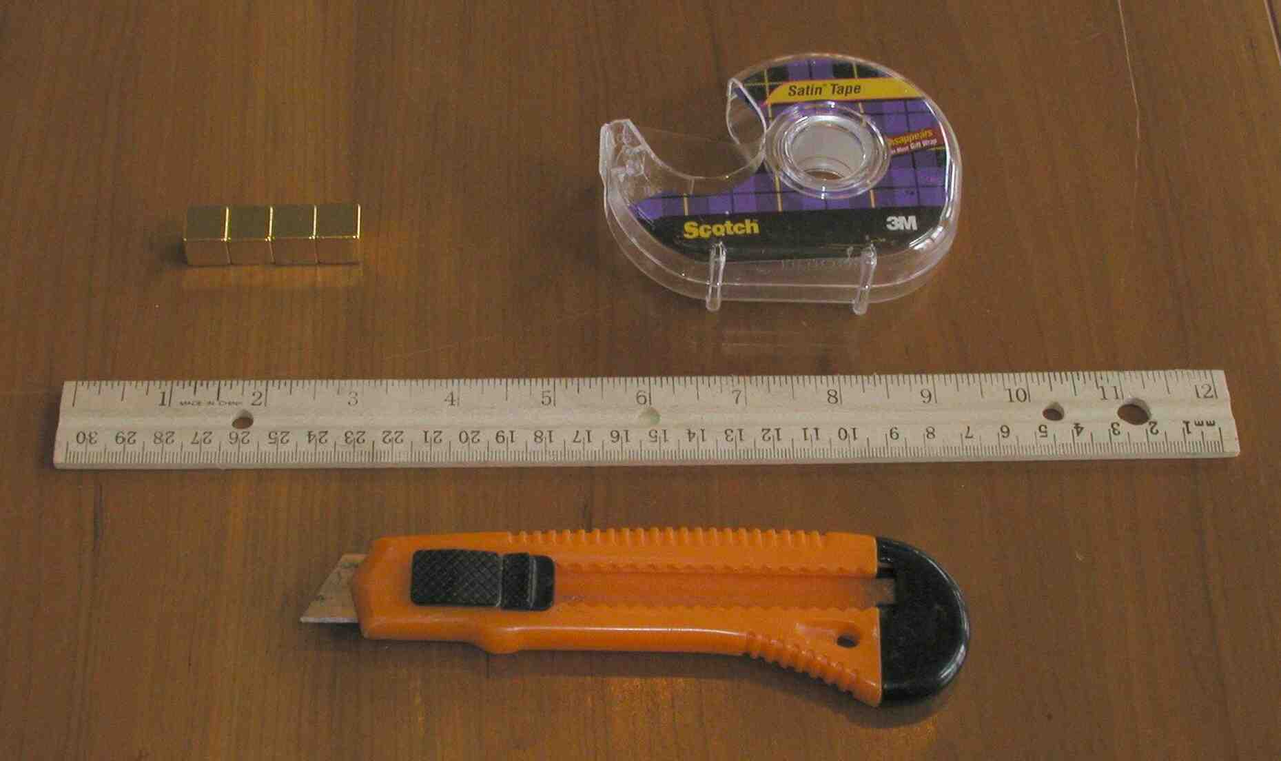 Click on image for larger view
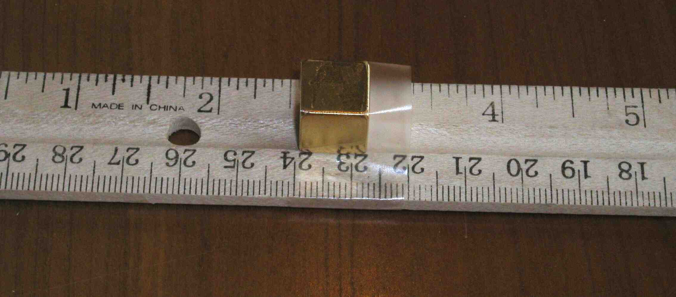
Click on image for larger view
Click on image for larger view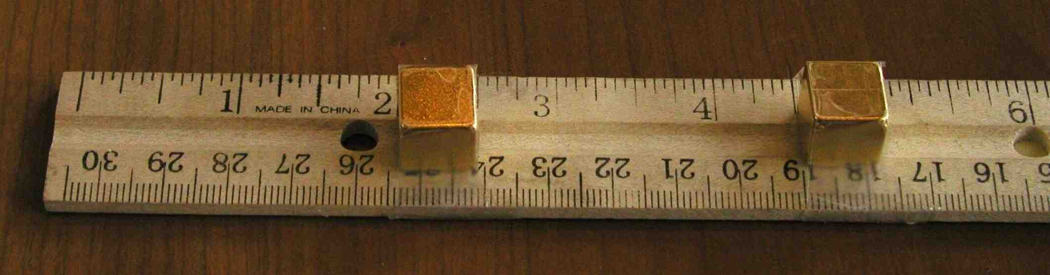
Click on image for larger view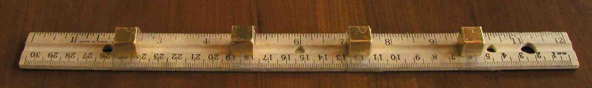
Click on image for larger view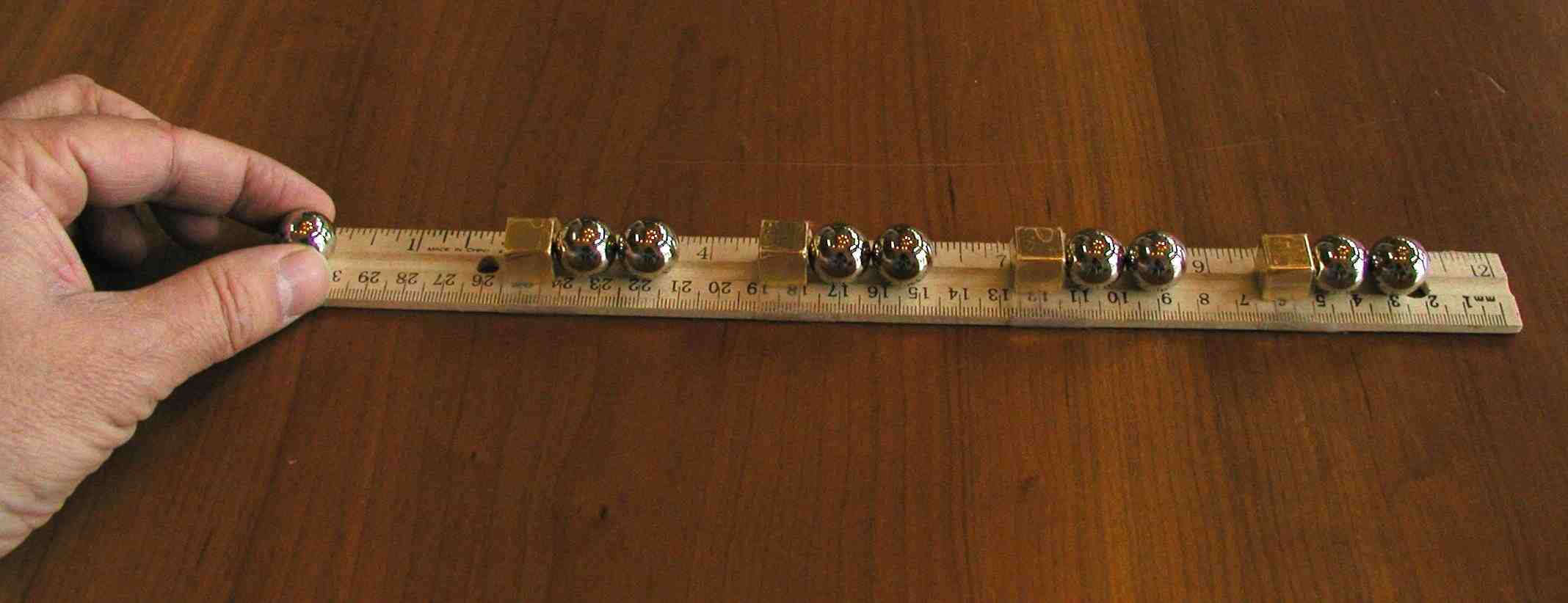
Click on image for larger viewHow does it do that?
Another way of looking at the mechanism
Speed and kinetic energy
Why a circular track will not be a perpetual motion device

Click on image for larger view
There are some materials that are more diamagnetic than bismuth. These include superconductors (which at this time require cryogenic temperatures to work), and similar materials that exhibit "giant diamagnetism" (also at very low temperatures).
But there is one material that is more diamagnetic than bismuth at room temperature, at least in one direction. That material is calledpyrolytic graphite.
Pyrolytic graphite is a synthetic material, made by a process calledchemical vapor deposition.
To make pyrolytic graphite, methane gas at low pressure (about 1 Torr) is heated to 2000 degrees Celsius. Very slowly, (one thousandth of an inch per hour) a layer of graphite grows.
The graphite made this way is very highly ordered, and the layers of carbon atoms form like a crystal of hexagonal sheets. These sheets lie on top of one another like sheets of mica. You can separate the layers with a sharp knife to make thinner sheets.
Click on image for larger view
Pyrolytic graphite is more diamagnetic than bismuth, but only in the direction perpendicular to the sheets of carbon. In other directions, it is still diamagnetic, but not as good as bismuth.
Because the density of pyrolytic graphite is lower than bismuth, (the specific gravity is 2.1), it is light enough to be levitated above a sufficiently powerful magnet. A thick piece will still be too heavy, since the material above about a half of a millimeter does not contribute much to the lift. But if the piece is thin enough, it will simply slide right off of a strong magnet, and refuse to sit still on it.
Click on image for larger view
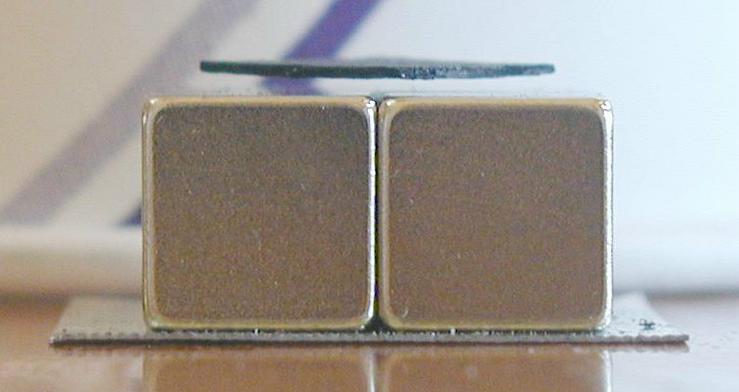
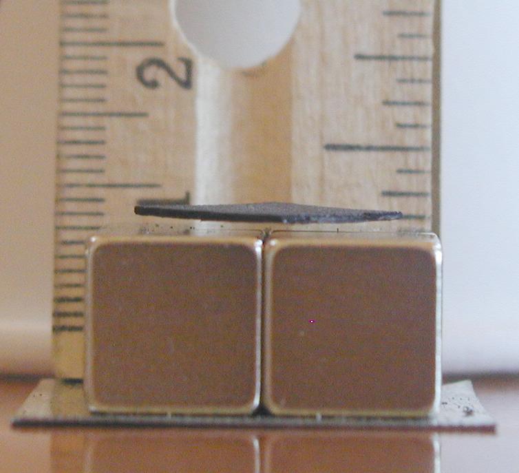
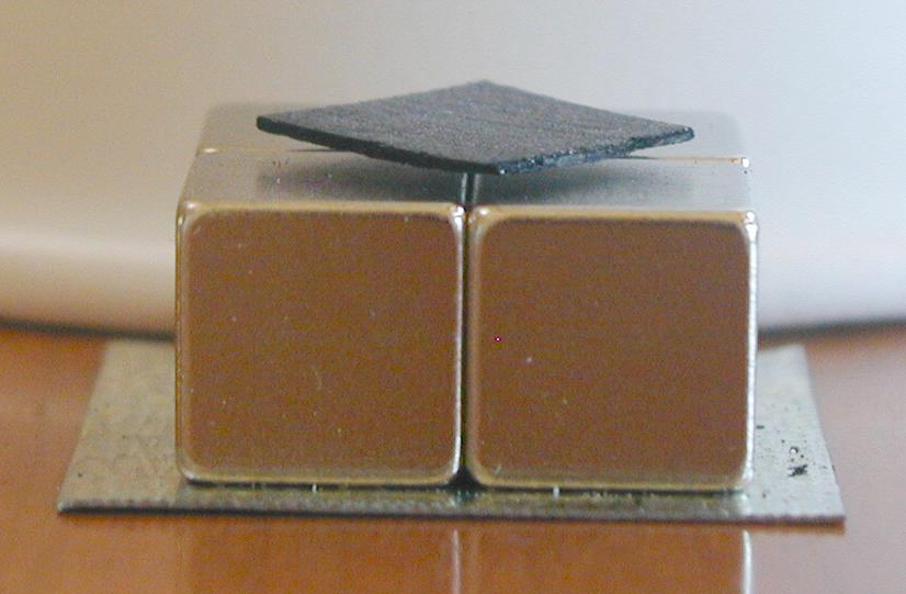
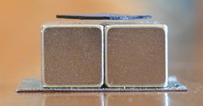
With a piece half a millimeter thick, using neodymium-iron-boron supermagnets, you can see from the photos that the piece is levitating about a millimeter above the magnets.
Click on image for larger view
To make the pyrolytic graphite plate sit still above the magnet, we need a way to force it towards the center.
We can do that by using four magnets. The poles of the magnets push on the diamagnetic material more strongly than other parts of the magnet. With four magnets, the four edges of the square of pyrolytic graphite will be pushed away from the four poles. If the square is slightly smaller than half the width of the four magnets (a little smaller than one magnet), then we can place it in the center, and it will be pushed to the middle and stay.
Click on image for larger view
Since diamagnetic materials are repelled by either pole, we can place the magnets with alternating north and south poles, and they will stick nicely to one another. I like to sit the whole array on a piece of sheet steel, so the magnets stay put.

This arrangement is discussed in excruciating detail on our Message Board.
The pyrolytic graphite plate floats above the magnets and springs back when you push it down with a finger.
Click on image for animated view
Since pyrolytic graphite is a little more diamagnetic than bismuth, it makes a great substitute for bismuth in the levitating magnet project.
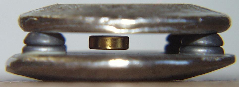
Below is a picture of a magnet spinning between two pieces of pyrolytic graphite, separated by a small piece of wood. The large magnet above it is not shown, but this is the same device we built earlier using bismuth.
Click on image for animated view
Pyrolytic graphite is not easy to find. The local hardware store won't be carrying it any time soon. But we carry it in our catalog, in pieces just the right size for the levitating magnet project.
These pieces are 16 millimeters wide, 32 millimeters long, and between a half millimeter to a millimeter thick. Split into thin sheets and then cut in half with a sharp knife to make 16 millimeter squares, they are perfect for levitating above four magnets.

Click on the photo to see a larger image
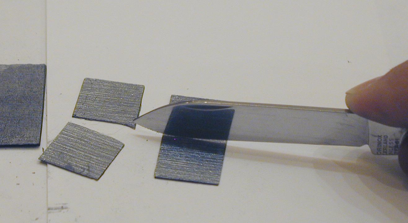
The knife should be very thin, so it splits the graphite cleanly, without breaking it. A razor blade or a utility knife would work better than the small blade of my swiss army knife, but the army knife works if you're very careful and practised at it.
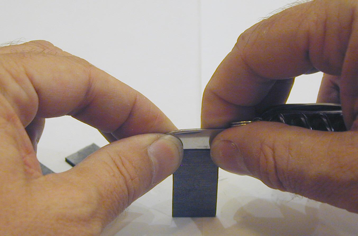
Click on the photo to see a larger image
Place the blade carefully in the middle of the edge of the graphite. Slowly push the blade in with a slight rocking motion. The graphite will make a nice clean sound as it starts to split.

Click on the photo to see a larger image
Sometimes you will get one thin piece and one thicker piece after they are split. You can often split the thicker piece again, giving you three pieces. If you are very skilled, you can get four pieces, but you will break a few gaining that skill.

Floating in mid-air between two metal plates, a tiny magnet bobs and spins in the wind from the viewer's breath.
No batteries are used, no electromagnets, no supercooled superconducting materials, just some easy to obtain materials from local stores.

Shopping list
- 12 ceramic ring magnets (Radio Shack)
- tiny neodymium-iron-boron magnet (Radio Shack) [The tiny rare-earth magnets shown in these photos are much stronger than the Radio Shack magnets, and can be found in our catalog. If using the Radio Shack magnets, you may need a stronger top magnet, and a taller support column.]
- 8 inches of 1/4 inch threaded brass rod
- 4 brass hex nuts to fit the 1/4 inch rod
- 2 brass or nylon washers to fit the brass rod
- wooden base (5 inch square, 3/4 inch high)
- 6 to 8 inch wooden support, 2 inches square
- 5 by 2 inch wooden block, 3/4 inch thick
- 2 tablespoons of Bismuth (non-toxic bird shot (from a gun shop or sporting goods store) [The bismuth shot shown in these photos can now be found in our catalog.]
- wood glue
- 1/4 inch drill bit and drill
- large cheap cooking spoon (we will ruin it)
- empty aluminum soda can
- coarse sandpaper or large metal file
- Titebond wood glue (or similar brand)
- 5 minute epoxy
Assembly
The heart of the device are the Bismuth plates. These are what make the magnetic suspension possible.
Bismuth is very similar to lead. It is easy to melt, and is as heavy and hard as lead. Because lead is toxic and bismuth is not (it is the active ingredient in the Pepto-Bismol medicine for upset stomach), it is used in environmentally safe bird shot for hunters. It is in this form that it is most easily found at gun shops and sporting goods stores. It can also be ordered on the Internet from
Precision Reloading.
[Since they only sell large quantities, we have obtained some and offer smaller amounts in our catalog.]
Bismuth is also used in some fishing lures as a replacement for lead.
This toy uses bismuth because of its special magnetic properties. [Don't forget to read the next page, where we do the same project with another substance called pyrolytic graphite.]
Melting and casting the bismuth
The first step in assembling the levitator is to melt the bismuth and pour it into a mold to make the two suspension plates. The mold is the bottom of an aluminum soda can, which has a convenient dimple that is about the right size.
You can use other molds if you wish, such as aluminum muffin tins, but remember that they will not be suitable for their normal uses afterwards. Don't use something the cook thinks is precious.
Place about a tablespoon of bismuth shot into the cheap spoon purchased for this purpose (don't use the cook's favorite spoon).
Heat the shot in the spoon over a stove or propane torch until it melts. A bit of coathanger wire can be used at this point to rake the slag (bismuth oxides) off of the top of the melted metal and onto the side of the spoon.
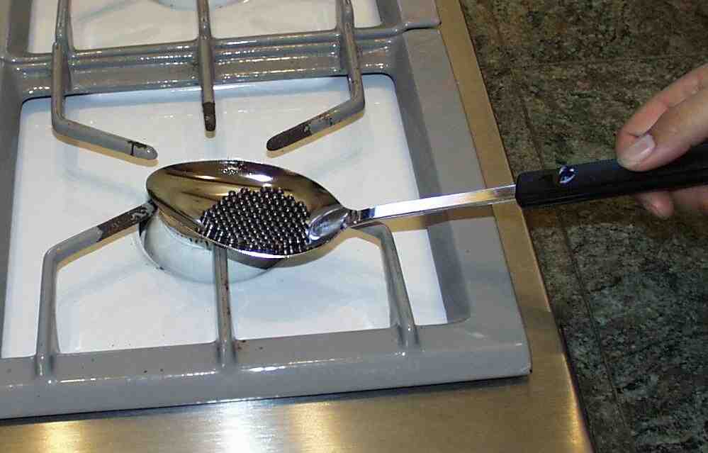
Next, carefully move the spoon over to the upside-down aluminum can, and pour the metal into the hollow in the bottom of the can.

Let the metal cool until it hardens, and the can is cool enough to hold. Only after the metal is completely solid can it be held under running water and pried out of the mold.

Use the sandpaper or a metal file to make the top and bottom surface of the metal nice and flat.
Make another bismuth disk like the first one.
Building the support structure
Drill a 1/4 inch hole in one end of the 2 inch by 5 inch block, about 3/4 of an inch from the edge. This will accept the brass rod.
Glue the 6 inch 2 by 2 support block to the base.
Glue the 2 by 5 block to the top of the support block, leaving the end with the hole free.
Allow the glue to dry. If you are very sparing with the glue, using only a very thin layer, the drying will only take a few minutes. I use Titebond wood glue.
Assembling the magnet stack
Insert the brass rod into the hole in the wood block.
Thread one nut onto the rod from above, and two from below.
Place a washer onto the rod from below, followed by the twelve magnets, and another washer, then the final nut.
The last nut should be close to the end of the rod. Tighten it by hand so as not to shatter the ceramic magnets. Don't worry yet about getting the top two nuts tight around the wood block, since we will be adjusting the height of the magnet soon.

Assembling the bismuth plates
The levitator is very sentitive to three things: the distance between the two bismuth disks, and the height and strength of the magnet above them.
The disks are kept apart by three spacers. These can be made from three pieces of bismuth shot, although wood or plastic would work fine.
The spacing between the disks should be very close, leaving only a very small space for the magnet. If the distance is too far, the magnet will jump from the bottom to the top, or fall from the top to the bottom, instead of floating between the disks in mid-air. If the magnets are very strong and far away, the distance between the bismuth disks can be increased.
Using the 5 minute epoxy, glue the three pieces of shot to the bottom bismuth disk, as far away from each other as possible, in an equilateral triangle.
Once the epoxy has completely hardened (give it 10 minutes to be safe) start filing or sanding the tops of the shot, to make them just tall enough so the tiny neodymium magnet can fit with only a little room to spare. If you stack two of the tiny magnets together, they should just fit, touching both plates (only one magnet will actually be used).
Adjusting the magnets for levitation
Hold the top bismuth disk in one hand, just under the stack of ring magnets. Let the small neodymium magnet stick to the bottom of the bismuth disk, attracted to the ring magnets.
Now set the top bismuth disk onto the three supports on top of the bottom disk. The tiny magnet may drop to the bottom disk, or it may remain stuck to the top disk.
If the tiny magnet falls to the bottom disk, lower the ring magnet assembly slowly by turning the rod while holding the top nut.
If the tiny magnet remains stuck to the top disk, raise the ring magnet assembly by turning the rod and holding the top nut.
At one point while turning the rod, the magnet will start to levitate between the disks.
The levitating disk is very sentitive to slight changes in the height of the ring magnet assembly. The rod must be turned very slowly to make tiny adjustments to the height of the neodymium magnet.
How does it do that?
The bismuth disks are diamagnetic. This means that they push away from a magnet. It doesn't matter whether the north pole of the magnet or the south pole is used, the bismuth always pushes away.
The diamagnetism is very weak, even in bismuth, which has the strongest diamagnetism of any metal. This is why the adjustment is so sensitive.
The ring magnets attract the small neodymium magnet with just exactly the right amount of force to counteract gravity. However, if the bismuth disks were not there, the tiny magnet would jump up to the ring magnets, because as it gets closer, the force is stronger.
Right at the critical point, where the magnetic pull just barely counteracts gravity, the weak diamagnetism of the bismuth is enough to keep the magnet from jumping up to the ring magnets, or falling down. The magnet thus floats, being repelled by the top and bottom bismuth disks.
Troubleshooting
The most common problem in building the device is that the floating magnet will either stick to the top bismuth plate, or stick to the bottom bismuth plate, but never hover in between them.
That happens because the plates are too far apart for the strength of the top magnet. You can either put the plates closer together, or (better) make the top magnet stronger by adding more magnets, or using more powerful magnets, or both.
The stronger the top magnets, the farther they can be from the floating magnet and still lift it. As the top magnet gets stronger and farther away from the floating magnet, the area where the floating magnet can be stabilized increases. The magnetic field is bigger and spreads out more, and so the floating magnet can move up and down more before the strength of the field changes enough to make it fly up or fall down. We say the rate of change of the magnetic field gradientis weaker if the top magnet is farther away. The gradient is just how much the strength of the field changes with distance.
A video
Below is a picture of a slightly different model I built, where I embedded brass wire into the bismuth before it cooled. This is a little harder to adjust than the first model, since the brass wire is springy, but it works pretty well. The floating magnet is a tiny gold plated cube of neodimium-iron-boron supermagnet, so the faces of the cube catch the light as it rotates. (These are available in our catalog.) If you click on the picture, you can see it move in the video.

I originally built this toy using a Canadian nickel coin. Canadian nickels are made of pure nickel, unlike U.S. nickels, which contain so much copper that they are not magnetic. You can build the toy with the nickel or with the Radio Shack rare-earth magnet. The rare earth magnet will work a little better because it loses its magnetic properties at a lower temperature, and thus the toy can use a candle instead of an alcohol burner for its heat source. Some particularly nice tiny rare-earth magnets can be found in our catalog. This heat engine is very simple. We suspend a small piece of magnetic material at the end of a pendulum. A large magnet is placed near the pendulum, so that the small piece of material sticks to the large magnet. The magnet should be close enough that the material never rests at the bottom of the pendulum's swing, but instead jumps up to the magnet. A candle is placed under the material, so the flame just touches it. The candle flame will heat up the magnetic material until it loses its ability to be magnetized. Gravity will then pull it away from the magnet (and thus away from the flame). The magnetic material will cool down a little bit once it is away from the flame, and regain its ability to stick to the magnet. The magnet will then pull it up into the flame, and the whole process repeats. All the parts can be found at Radio Shack, but if you want to build the engine using a Canadian nickel, any hardware store will have the other parts you need. You will need some copper or brass wire, a large ceramic magnet (the cheap kind that Radio Shack sells for about a dollar), and a candle. We want the pendulum to swing back and forth only, so we use two wires to hold it up. Cut about a foot of wire and wrap the center of the wire around the large magnet. Then form the two ends into small loops and bend them up to form the support for the pendulum. If you are using the rare-earth magnet for the pendulum's weight, it helps at this point to demagnetize it by holding it in a candle flame. You can stick it onto a coat hanger and hold the magnet in the flame until it falls off. This will prevent the magnet from jumping onto the large ceramic magnet while we adjust the pendulum. Wrap another foot of wire around the nickel or the rare-earth magnet that will form the weight for the pendulum. Form the two ends of the wire into loops that slip into the loops of the pendulum support. Make sure that the pendulum weight is just close enough to the magnet that it rises to it when the pendulum is vertical. The wires of the pendulum and its support should be long enough that the weight can fall away from the flame and hang vertically when it is demagnetized. With the pendulum stuck to the large magnet, position a short (lighted) candle so that the flame just touches the weight. You may need to shield the flame from drafts so it remains steady. The flame will heat the rare-earth alloy until it loses its ability to stick to the large ceramic magnet. It will then fall away, and swing a few times as it cools. When it is cool enough to be magnetized again, it will rise and stick to the magnet, where the flame will again heat it up. If the weight still touches the flame when it has fallen away from the magnet, adjust the pendulum's supports a little so that the weight rests a little farther away. If the weight is so far away that the magnet cannot pull it back up once it is magnetized, adjust the supports to bring it closer. Be careful when adjusting the supports, since they may be quite hot. Also be careful to move the candle so as not to burn yourself on the candle flame. When the engine is adjusted just right, it will settle down to a predictable swing, often taking only one swing to cool enough to stick to the magnet again. It will run as long as the candle burns. If you have chosen to use the Canadian nickel, you will need a heat source better than the candle. A small alcohol lamp or fondue pot burner will do nicely. You may have to make the pendulum support wires longer to make room for the lamp. The heat engine works because of something called the Curie effect. The Curie effect describes how a magnetic material loses its ability to stick to a magnet when heated above a certain temperature. This temperature is called the Curie temperature, and varies with the material. The Curie temperature for iron is about eight hundred degrees Celsius. The Curie temperature for the inexpensive ceramic magnets is also quite high, which is why the candle flame or even the alcohol lamp does not affect them. The Curie temperature for the Canadian nickel is lower, about 631 degrees Celsius. This temperature is within range of the alcohol lamp, and almost possible with the candle. The Curie temperature for the Radio Shack rare earth magnets is 310 degrees Celsius, and the candle can reach this easily (not only because of the lower Curie temperature, but because the magnets are so much smaller than the nickel that they heat up faster, and have less unheated surface area). I have tried Ronson lighter flints, which also have a Curie temperature within easy range of a candle. The combination of their small size and low Curie point makes them stay above their Curie point too long. The magnet and the flame have to be close together for the engine to work. When the flints are close enough to the magnet to overcome gravity, they are close enough to the flame to rise above their Curie point. Other designs have been tried successfully, involving placing the flints on a wheel and using a soldering iron as a heat source. A magnifying glass could be used to focus the sun on the flint when it is touching the magnet, without heating the flint when it falls away. Experiment with other designs. There are many possibilities. Here are the construction details.
Why does it do that?
In 1919, Heinrich Barkhausen discovered that magnetizing a metal like iron is not a continuous process, but occurs in tiny jumps, which can be heard if a coil is placed around the metal and connected to an amplifier and a speaker. The clicks sound like a Geiger counter, and are generated as tiny areas in the metal (called magnetic domains) suddenly merge together. The equipment needed to hear these sounds is quite simple: We start by putting the washers and nut onto the bolt, and putting the threaded end of the bolt into the chuck of a variable speed drill. You can wind the coil by hand if you like, but the drill will speed things up considerably. Stick a few inches of the insulated magnet wire into the drill chuck next to the threaded end of the bolt, and start winding the wire around the bolt, between the two washers. Start out slowly, winding the wire around the bolt. You do not need to be neat about it — I made neat parallel windings so the photo would look nice, but random windings are much easier and faster to make, and the coil will work just fine if it looks a little lumpy, or even verylumpy. Slow down as the windings approach the washer at the end, so the wire will snug up tightly against it. Usually, even with great care, by the time you are half way done, the windings will start to have some small imperfections, just because it is tedious to wind the wire tight and close. Winding it fast and sloppy is a lot more fun. Once the coil is wound, strip off the insulation from the two ends of the wire, and solder a connector onto the ends so it can be plugged into your amplifier. You can hear the clicks in this video as I wave the magnet around near the coil. A high definition version of the video (82 megabytes) is available here. The metal in the bolt is made of many tiny crystals of ferromagnetic steel. A ferromagnetic material is one in which the atoms behave like small magnets. If a crystal is very tiny, all of the magnetic atoms in the crystal will have their north poles pointing in the same direction. If the crystal is a little larger (as most are in the bolt), the atoms will divide into small domains of magnetic alignment, so that one domain will have north pointing in one direction, and the other domain will have north pointing in the opposite direction. This opposite alignment keeps the south end of one domain near the north end of the other. The reason for this (and the reason why any pair of magnets will align this way when they can) has to do with energy. As we saw in previous projects, it takes energy to create a magnetic field. The energy is stored in the field. In nature, there is a tendency for things to settle into the lowest energy state. Thus if you use energy to lift a brick off the ground, it will tend to fall back to the ground and lose that energy if you drop it. The larger a magnetic field is, the more energy is stored in it. If all the atoms were magnetically aligned in the same direction, the magnetic field would be as large as it can get. If half of the atoms turned around the opposite way, there would be no net magnetic field around the metal, and the energy would be zero. So it is the natural tendency of atoms to align themselves in this lowest energy way. When we move a magnet close to the steel bolt, the atoms in the bolt align opposite to the atoms in the magnet. This reduces the size of the magnetic field around the magnet. The closer the magnet gets to the bolt, the more alignment occurs, and the smaller the magnetic field gets, losing energy. Just like the brick falls to the ground, the magnet and bolt "fall" together. We feel the tug of the attraction between the two. We can extract the energy from the magnetic field by letting it do work, such as raising the bolt off the ground. There are two things that prevent the atoms in the bolt from aligning perfectly at the atomic level. The first one is that there is an energy cost in building what is called the domain wall between areas of different alignment. The surface area of a domain grows with the square of the radius of the domain. The volume of the domain grows with the cube of the radius. The energy in the magnetic field depends on the volume of the domain. The energy in the domain walls depends on the surface area of the domain. As the domain gets smaller, the ratio of energy stored in the walls to the energy stored in the magnetic field gets larger. At a critical point, the energies are equal, and energy is required to make them smaller. At this point, no more energy can be had from making the domains smaller. This means that half the atoms in a large domain will flip, so there are two domains with their poles aligned opposite one another. If those two domains are still above the energy limit, they will also split into two, so there are four domains. This continues until all the domains are so small that no more energy can be lost by making them smaller. The second obstacle to perfect alignment and zero energy is that domains have difficulty forming across crystal boundaries, and across imperfections in the crystal itself. Since it requires energy to divide a domain in the presence of these obstacles, the domain stays larger than it would otherwise be. If we put energy in, by moving a nearby magnet, the obstacle is overcome, and the domain suddenly either divides in two, or grows by flipping a neighboring domain into alignment. This sticking and slipping is what we hear as clicks from the speaker. This sticking of domains is why some metals become permanent magnets. If we place them in a magnetic field, the domains align. When the field is removed, some of the domains have enough energy to overcome the obstacles will align opposite. But many of them remain stuck, and the metal has a permanent magnetic field as a result.What you need
 Click on image for a larger picture
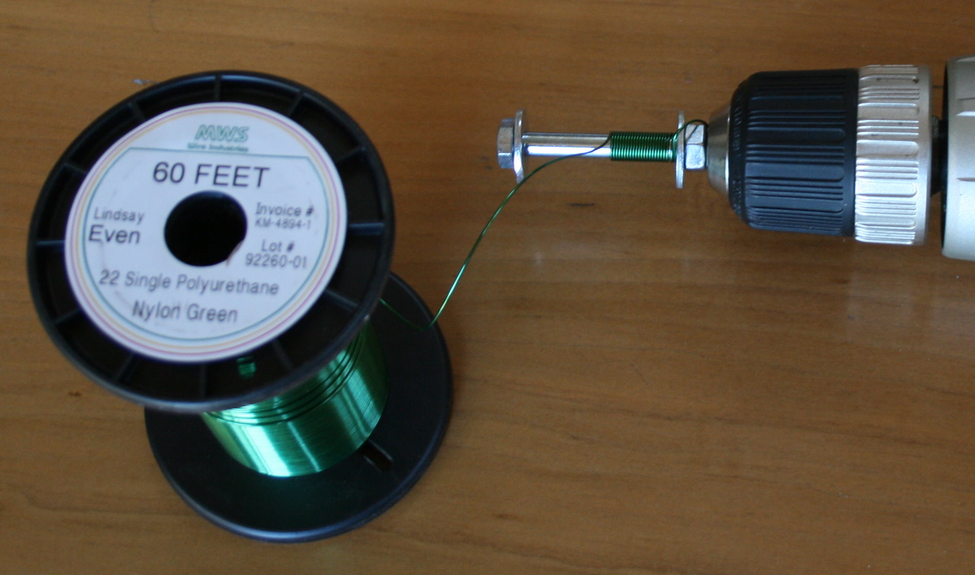 Click on image for a larger picture
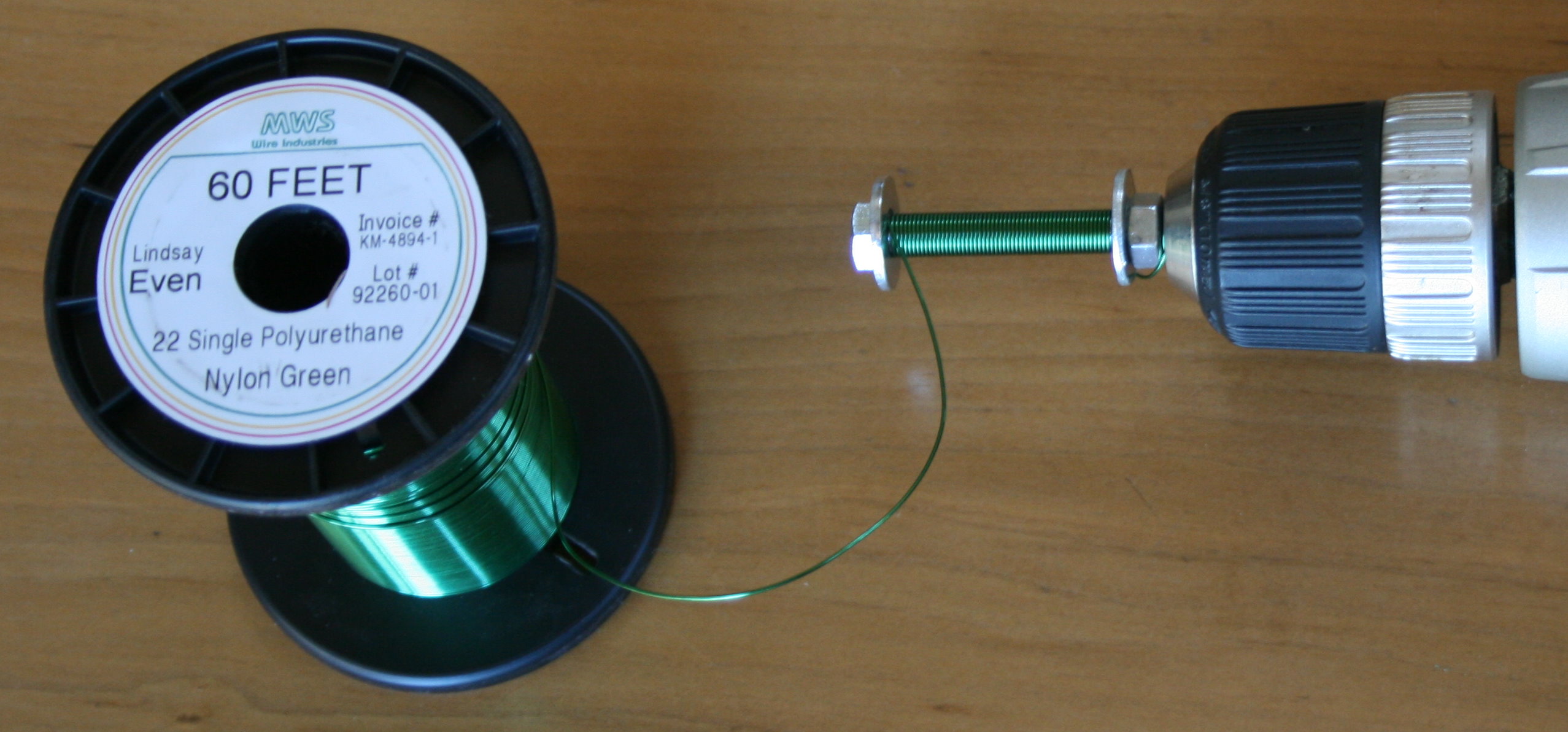 Click on image for a larger picture
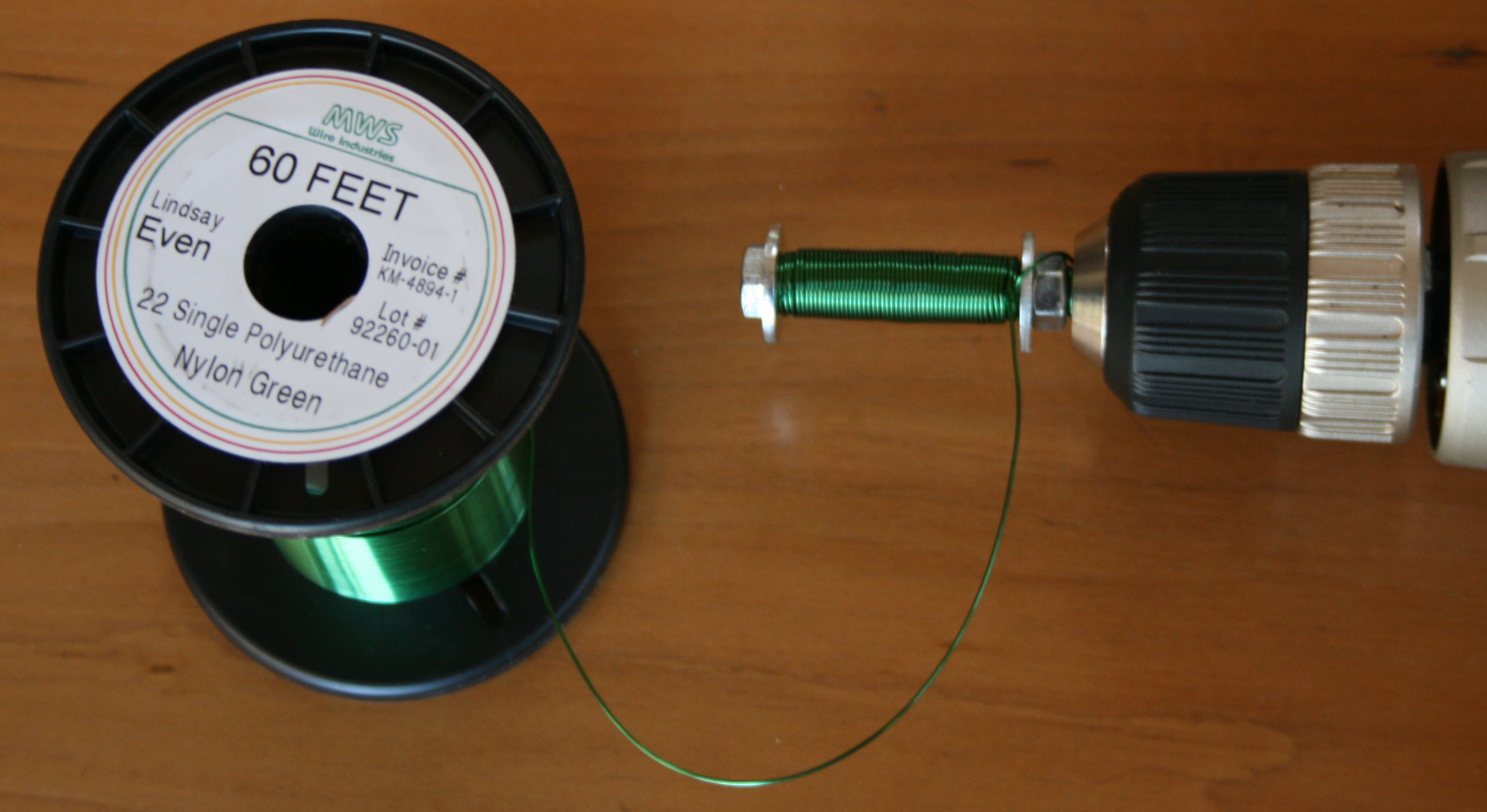 Click on image for a larger picture
 Click on image for a larger picture
How Does It Do That?